Skip to content

The design code: WSA 04

In Australia, sewer pump stations that will be handed to a water agency are usually designed to WSA 04, the Sewage Pumping Station Code of Australia, published by the Water Services Association of Australia (WSAA).

Most water agencies add their own requirements to WSA 04, such as preferred pumps, controls, emergency storage and approved products. Always design to the code edition and the local requirements the asset owner names.

Products used in the station are often checked through WSAA's national product appraisal scheme. Mullaly FRP sewage pump stations and emergency storage tanks hold appraisal PA 1020 (Issue 4, valid to 20 April 2031), covering external diameters from 1.2m to 4m and depths to 14m, and are designed to WSA 04.

What the design has to settle

Whatever the material, a sewage pump station design works through the same questions:

  • Flows. The catchment's dry weather and wet weather design flows, now and at full development, set the pump duty.
  • Pumps and pressure main. Pump selection, the number of duty and standby pumps, and the pressure main size and route follow from the flows and the system head.
  • Wet well. Diameter and depth, start and stop levels, and the volume between them (see below).
  • Emergency storage. How long the station must hold inflow if the pumps or power fail, and whether that storage sits in the wet well, in the incoming sewer or in a separate tank.
  • Valves and pipework. Isolation and non-return valves, scour and bypass lines, and how they are reached for maintenance.
  • Structure. Ground and groundwater loads, surface and traffic loads on the lid, and flotation.
  • Access, safety and odour. Covers, lifting for pump removal, ventilation, and limiting confined space entry.
  • Maintenance. How the station will be inspected, cleaned and serviced over its life (see below).
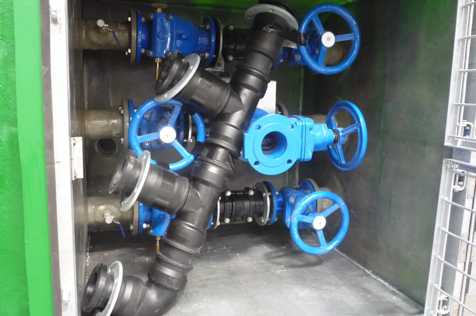
Gate valves and discharge pipework inside the valve chamber of a Mullaly FRP pump station

Wet well design and sizing

The wet well has to do three jobs: give the pumps enough submergence to run properly, store enough volume between the start and stop levels that the pumps do not cycle too often, and fit the pumps, guide rails and pipework with room to lift a pump out.

Depth

Depth is set mostly by the invert level of the incoming sewer. Below the inlet you need the operating volume, the pump stop level above the minimum submergence the pump maker sets, and the floor. Deep inlets make deep wet wells; the Mullaly standard range runs from 2m to 14m, with deeper units on request.

Operating volume

The volume between the pump start and stop levels controls how often each pump starts. Too small and the pumps start more often than the pump maker allows; too large and sewage sits long enough to turn septic and cause odour. Check the allowable starts per hour against the pump data and the agency's supplement.

Diameter

Diameter follows from the plan area needed for the operating volume over the available depth, and from the space the pumps, guide rails, pipework and access hatch need. Two or more pumps (duty and standby) need room for each to be lifted out separately. A divided wet well, with an internal wall forming two pump chambers, lets half the station be isolated for maintenance; Mullaly built one at Innes Estate.

Emergency storage

Emergency storage holds inflow during a power or pump failure. Where the wet well and incoming sewer can't hold the required volume, a separate storage tank is added beside the station. Mullaly FRP emergency storage tanks from 5,000L to 150,000L are covered by the same WSAA appraisal as the pump stations.

Flotation

An empty wet well in high groundwater is buoyant. The design has to show the station will not float, using ballast, a base slab or anchors. Mullaly supplies ballast calculations to counter hydrostatic uplift with the installation instructions for each pump station.

Mullaly fibreglass wet well options

ItemDetail
Standard modelsME150, ME180, ME200, ME250, ME275, ME300, ME375 (1.5m to 3.75m diameter)
Depths2m to 14m, deeper on request
Larger unitsEngineered to project, for example a 4.0m diameter, 8.5m deep wet well at Innes Estate
ConfigurationsCombo (wet well and valve pit in one unit), separate wet well and valve pit, divided wet well, wet well, valve pit and macerator combo
StructureDesigned as a stand-alone unit for the internal and external loads on the site by a registered practising composite engineer. Roof loads are taken by a reinforced concrete slab spanning the station
LaminateVinyl ester resin. Inner and external 0.5mm corrosion layers with C-glass or synthetic tissue, either side of an E-glass structural backing layer
CoversAluminium lockable hinged lids and safety grates to AS 1664 (pedestrian), or ductile iron Class B, Class D (vehicular) or Class G
Fit-outPedestals, guide rails, pipework and valves fitted in the factory to the approved drawings
Design life and warranty100-year design life; 30-year limited product warranty

Full details are in the fibreglass pump station technical data sheet (TD_TDS_020).

Combo or separate valve pit

A combo pump station builds the valve chamber into the wet well. It shortens excavation, needs less space, and there is no differential settlement between the wet well and the valve pit, because they are one structure. A separate wet well and valve pit suit stations that need a larger wet well diameter, or where transport limits rule out taking a combo to site. Lotus Glen (a 3.75m diameter, 9.03m deep wet well with a separate 1.8m x 2.2m x 1.75m valve pit) is an example.

Working with Mullaly on a design

  1. 1

    Send the specification

    Send us the design or specification: inflows or the wet well size you need, inlet invert and finished surface levels, pump make and model, valve arrangement, cover loads and groundwater level.

  2. 2

    Review the drawings

    We prepare CAD fabrication drawings showing the layout, every fitting and connection, and all levels, for your approval. A fit-out pipework specification is available on request.

  3. 3

    Manufacture and fit-out

    The station is made in one piece in our Tomago factory and fitted out to the approved drawings.

  4. 4

    Delivery and installation

    The station arrives ready to place, with installation instructions and ballast calculations.

Pump station maintenance

A sewer pump station is maintained for its whole life, so plan for maintenance at the design stage. Routine pump station maintenance usually includes:

  • Checking pump operation, run hours, starts and alarms, and the level controls that switch the pumps.
  • Removing rags, grease and solids that build up in the wet well, and cleaning level sensors and floats.
  • Lifting each pump out on its guide rails for inspection and servicing.
  • Operating the isolation and non-return valves and checking the valve pit for leaks.
  • Checking covers, safety grates, ventilation and any odour control.
  • Inspecting the wet well walls, fittings and pipework for corrosion or damage.

The asset owner's requirements and the pump and valve makers' manuals set the actual tasks and intervals. Design choices decide how easy they are: guide rails and lifting points let pumps come out from the surface, a valve pit or combo station keeps the valves reachable without entering the wet well, and a smooth, corrosion-resistant wall holds less build-up. Mullaly wet wells are made with vinyl ester resin that resists the corrosive chemicals in sewage and needs no coating or liner, and their smooth internal walls stay cleaner for longer. See fibreglass and concrete pump stations compared for how the two materials differ in service.

Related pages

See sewage pump stations and stormwater pump stations for the product range, fibreglass wet wells and valve pits and access chambers for the parts of a station, and the resource centre for data sheets and installation guidelines.

Download the pump station brochure

Enter your email and the brochure opens straight away. We will also email you the link.

Talk to us about a pump station design

Send us your specification or drawings and our team will come back with a design and quote. We reply to every enquiry within 2 business days.

Or call 02 4964 8270 or email sales@mullaly.com.au

Newsletter